
Control points (also called surveyed points, datum points, or simply "control") are fixed reference marks on a jobsite with known coordinates. They tie the digital layout file to the real-world building so the FieldPrinter prints every line in the correct position and at true scale.
This article explains what control points are, why Dusty needs them, the types Dusty can use, how Dusty best-fits your layout to them, and the file formats Dusty accepts. It's written for VDC teams, surveyors, and field crews.
What Is a Control Point?
A control point is a physical marking with known X, Y, and Z coordinates (surveyors often call these Easting, Northing, and Elevation). A set of control points is called a control network.
Control points do three things:
- Give the laser tracker and the FieldPrinter a way to know exactly where they are on the slab.
- Anchor the digital layout file to the real-world jobsite.
- Give every trade a shared reference, so walls, sleeves, embeds, and equipment all align to the same system.
Think of control points as permanent measuring-tape zeroes that everyone on the project agrees on. They are set by a surveyor or layout team, they don't move during construction, and every trade references the same points.
Why Dusty Needs Control Points
Construction drawings live in a digital coordinate system; jobsites live in the physical world. Control points are the shared anchors that exist in both places — in the AutoCAD or Revit file, and physically on the slab, walls, or columns.
Dusty uses a laser tracker to take measurements from point to point. During setup ("stationing"), the tracker records the control points, and Dusty aligns the layout to them. The robot doesn't guess its position — it calculates it from the control network.
Because the tracker needs a clear line of sight, it may need to be re-stationed as the robot moves around columns, walls, materials, or other obstructions. For each station, the tracker must be able to see at least three control points.
How Best-Fit Alignment Works
The CAD file and the laser tracker each work in their own coordinate system. The Dusty App applies rotations and translations to bring the tracker's coordinates into alignment with the CAD coordinates. The layout is never scaled — it always keeps its true dimensions, so the printed layout is always produced at a true 1:1 scale regardless of small or big errors in the control points.
Dusty aligns the two sets of points using a method called least squares best-fit:
- Dusty takes both sets of points. You need at least 3 control points that don't all fall on one line. More than 3 is better.
- It finds the geometric center of each set. The center of your CAD points and the center of your scanned points each become a pivot.
- It slides one center onto the other. This is the shift, or translation.
- It rotates the scanned set onto the CAD set. Dusty solves directly for the single rotation that makes the total leftover gap across every recorded point as small as possible — a standard least-squares fit.
- It reports what's left over. Whatever gap remains at each point after the best possible fit is the error you see for that point in the app.
The leftover differences are the error values and difference values shown in the Dusty App. Because the fit is averaged across every point you record, recording more than the 3-point minimum improves accuracy. Extra points give best-fit more samples of the jobsite and dilute the effect of any single point that's slightly off.
Types of Control Points
Horizontal control points
Most control points are marked on flat, horizontal surfaces. The reflector sits on a control point target placed over the mark. Common compatible types:
| Control point type | Reflector tooling needed | Notes |
|---|---|---|
|
Intersection of grid-line offsets |
Control point target |
Accurate if surveyed |
|
Point mark on floor |
Control point target |
Accurate if surveyed |
|
Arrow mark on floor |
Control point target |
Accurate if surveyed |
|
Drift nest on column |
Drift nest |
Accurate if surveyed |
|
Target on wall |
Drift nest or vertical control target |
Accurate if surveyed |
|
Hole |
Pin nest |
Accurate if surveyed |
Not compatible with the FieldPrint platform: survey pins and survey stakes — there is no reflector nest for these.
Not recommended: marks on unstable or small surfaces (the surface should be at least 3" across so the target rests stably), and thick cross marks (hard to place the reflector precisely, which causes inconsistency after re-stationing).
Vertical control points
Control points can also be placed on walls or columns instead of the floor — common in data centers and manufacturing/distribution plants. Because the laser tracker measures to the center of the reflector sphere, vertical control requires a small offset (about 1-1/4") to be applied so the coordinates line up. Dusty offers a purpose-built vertical control target with the offset built in.
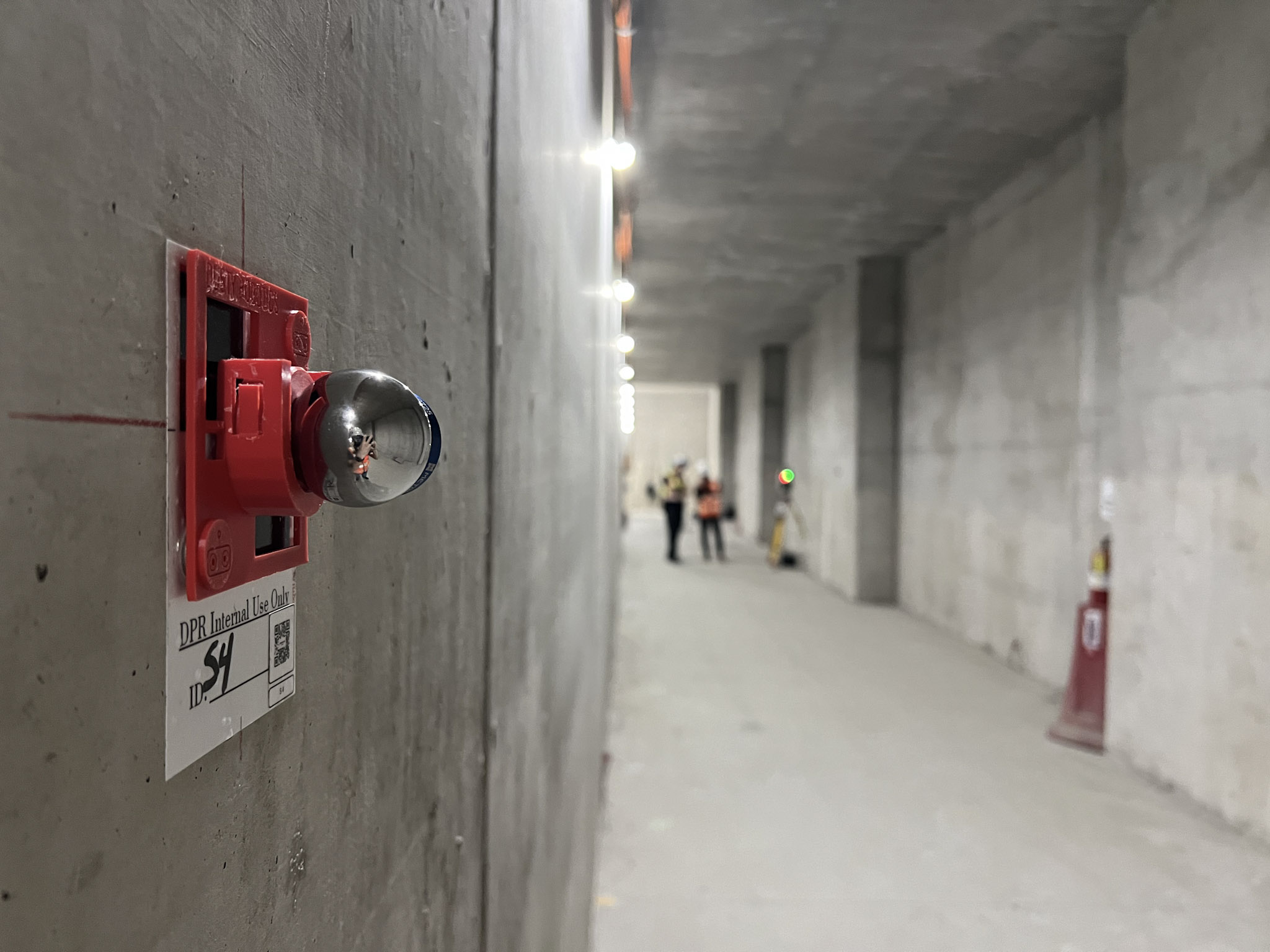
For the full workflow, see How to Use Vertical Control Points for Accurate Layout.
When you don't have surveyed control
Dusty doesn't require a specific survey instrument or brand, and it can work on imperfect jobsites that don't have clean surveyed control — using tools like Create Control at Reflector, Persistent Control, and Corner Control. See What Is Flexible Control? Stationing Tools for Imperfect Jobsites.
Control Point File Formats
Dusty accepts control points in two ways:
1. CSV file (most common)
Control points are delivered as a CSV file uploaded to the Dusty Portal. The format is flexible on header wording:
- Minimum 4 columns: a point-name column, plus X, Y, and Z coordinate columns. A description column is optional.
-
Header matching (case-insensitive, spaces and a "(ft)" suffix ignored):
- Point name — header contains
pointorname(e.g.,Point Name,Point,Name) - X — header contains
xoreast, or is exactlye - Y — header contains
yornorth, or is exactlyn - Z — header contains
z - Description (optional) — header contains
desc
- Point name — header contains
- Column order can be X, Y, Z or Y, X, Z.
- Coordinates must be plain numbers (no comma thousands separators, no text like "N/A"). Units default to feet on upload and can be changed to inches or meters in the import dialog.
- Coordinate system must match the layout file being published to the Dusty Portal.
2. Marked in the DWG file
Control locations can be indicated in the DWG using crosshair linework showing the intended X/Y intersections. These are used as a field reference to create the control points on-site with the iPad; the DWG geometry itself is not read directly as control input. Coordinates can also be exported from AutoCAD to a CSV using Dusty's LSP export tool or AutoCAD Data Extraction.
How Many Control Points You Need
Dusty requires a minimum of 3 non-collinear control points per station (they cannot fall in a straight line, and cannot form the answer with fewer than 3). More than the minimum is strongly recommended — additional points give best-fit more samples of the jobsite, improve accuracy, keep the layout consistent between stations, and protect you if one point is blocked or covered. Spread the points out so they surround the print area, and include points from previous setups when you re-station.
Selecting Control Points For Best Accuracy | |
|
Scan control points that are far away.
Errors only cover the area between recorded control points. When your control points are spaced far apart, you can print accurately over a larger area - even if the shown error is higher than with closer points. |
|
|
|
More recorded points is always better.
It is better to have five control points with an 1/16" station error than only three with smaller errors. The more control points you have, the more accurate your print alignment will be. |
|
Record control points around your print area.
To make sure your control points are spaced out properly, set them up around the area that you plan to print. |
|
Related Articles
- What Is Flexible Control? Stationing Tools for Imperfect Jobsites
- How to Use Vertical Control Points for Accurate Layout
Good control is the foundation of accurate layout. Dusty makes that accuracy visible and measurable — but it starts with solid control points.