
A laser tracker finds the reflector on your FieldPrinter by measuring three things at the same time — a horizontal angle, a vertical angle, and a distance along the beam — and then steering itself to keep the beam centered on the reflector as the robot moves. Those three numbers are a position in space. Everything else the tracker does is in service of taking them accurately, thousands of times over the course of a print.
The three measurements that become a position
Think of the tracker's head as the origin point. To locate the reflector it needs:
- A horizontal angle — how far around, left or right.
- A vertical angle — how far up or down.
- A distance — how far out along that line.
Two angles fix the direction. The distance fixes how far along that direction the reflector sits. Together they are a single point, which the software converts into the same coordinate system as your layout file.
Each of the three is a separate measurement made by separate hardware, and each carries its own error. They are not equally accurate, and the difference between them is the single most useful thing to understand about the instrument.
Why the distance is the accurate measurement and the angles are not
The distance measurement is ten to twenty times more accurate than the transverse (side-to-side) measurement, depending on which tracker you have, and that gap widens the farther the reflector is from the tracker.
Leica publishes both figures as Maximum Permissible Error. At 100 ft (30.5 m) from the tracker:
| Measurement | Published Maximum Permissible Error | At 100 ft (30.5 m) |
|---|---|---|
| Distance, along the beam | ±10 μm, plus up to 0.3 μm per metre | about ±0.01 to ±0.02 mm (±0.0004 to ±0.0008 in) |
| Transverse, across the beam | ±15 μm + 6 μm/m | about ±0.20 mm (±0.008 in) |
The distance figure barely grows with range — at most 0.3 μm for every metre, and on some trackers it does not grow at all. The transverse figure grows at 6 μm per metre, at least twenty times faster. That is the nature of an angle: a fixed angular error sweeps a wider and wider arc the farther out you go.
The practical shape of this is an error zone around the reflector that is very short in the direction of the beam and much wider side to side. Close to the tracker it is nearly a point. At long range it stretches out sideways.
What this means while the robot is printing
The FieldPrinter is most accurate when it is printing across the tracker's line of sight, because in that direction the robot's position is governed by the precise distance measurement. When it prints directly toward or away from the tracker, the transverse measurement is doing more of the work, and that is the direction where error grows with range.
You do not manage this by hand. It is worth knowing because it explains why a wavy or drifting line, when one shows up, usually shows up far from the tracker rather than near it.
How the tracker measures distance
Both of Dusty's trackers use absolute distance measurement. The distance module sends out an invisible infrared beam whose polarization is modulated in a known pattern, and reads that pattern on the beam coming back off the reflector.
"Absolute" is the word that matters on a jobsite. An absolute measurement gives the full distance to the reflector on its own, from nothing — as opposed to a method that has to count continuously from a known starting point and loses its place the moment the beam is broken.
That is why an interruption is recoverable. Someone walks through the beam, a pallet gets set down in the line of sight, and the tracker does not need to be walked back to a reference position. On the recovery itself, the tracker's automatic target acquisition finds the reflector and steers the beam back onto it without operator intervention.
How the tracker follows a moving reflector
The tracker does not have to be aimed by hand once it has found the reflector. The beam that comes back off the reflector lands on a sensor inside the instrument. If the reflector has moved, the returning beam lands off-center. The tracker measures how far off-center, converts that into a steering offset, and drives its motors to re-center the beam — continuously, as a closed loop.
This is what "tracking" means, and it is why the instrument can hold a lock on a robot that is driving and printing at the same time.
What the reflector contributes
The tracker is only half the system. The reflector on the FieldPrinter is a precision optic in its own right: three mirrors at right angles to each other, centered inside a metal ball. That arrangement sends the beam back toward the tracker across a range of entry angles, and the ball gives a constant, known offset from whatever the reflector is sitting against. Together they let the tracker measure to a single fixed point no matter how the robot is oriented.
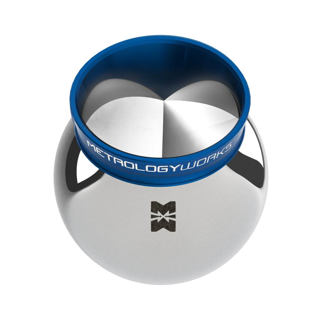 |
A scratched, dirty, or damaged reflector degrades accuracy without producing an error message. See How the Reflector (SMR) Works and What Damages the Reflector and How to Catch It.
What the air between the tracker and the reflector does to the reading
The beam travels through air, and air is not a constant. Leica publishes how much the distance reading shifts with conditions:
| Condition | Effect on the distance measurement |
|---|---|
| ±1 °C change in air temperature | about 1 ppm |
| ±4 hPa change in air pressure | about 1 ppm |
| ±30% change in relative humidity at 40 °C | about 1 ppm |
| ±30% change in relative humidity at 20 °C | about 0.3 ppm |
| ±30% change in relative humidity at 0 °C | about 0.1 ppm |
One part per million is one millimeter per kilometer, so at layout distances these corrections are small. The tracker measures conditions with a built-in probe and applies the correction for you — you do not enter temperature and pressure by hand.
Hot air rising off concrete in direct sun is not uniform. It bends the beam by different amounts from moment to moment, and the effect shows up in the tracker's pointing rather than in its ranging: the reflector appears to shimmer and wander, which is the measurement that was already the weaker of the two. That is why heat problems present as waviness and lost locks. See Why Heat Shimmer Stops the Laser Tracker From Locking Onto the Reflector.
How to read the accuracy numbers on a spec sheet
Laser tracker accuracy is published as Maximum Permissible Error (MPE) under ISO 10360-10. This is not the error you should expect. It is the largest error the instrument is permitted to produce and still pass its acceptance test.
Leica states in both manuals that typical measurement results are half the relevant MPE value. So the ±0.20 mm transverse figure at 100 ft is a ceiling; a working instrument in good condition typically lands near half that.
Two other things the numbers do not say:
- Tracker accuracy is not layout accuracy. The tracker is one contributor. Control point quality, slab flatness, tripod stability, and the robot itself all add error on top. Dusty's published layout accuracy standard is the number that governs your job.
- MPE figures assume the conditions of the test. Distance, temperature, and a clean reflector in good condition are all part of the picture.
Where the tracker's accuracy is set, and where it isn't
The tracker's own precision does you no good if it does not know where it is standing. That is what stationing does — it measures known control points and solves for the tracker's own position and orientation in your project's coordinate system. A perfect instrument stationed off bad control produces confidently wrong layout.
This is why control point quality gets the attention it does. See What Are Control Points and Why Dusty Needs Them and How to Select Control Points for Better Stationing Accuracy.
Related Articles
- How the Reflector (SMR) Works
- What Are Control Points and Why Dusty Needs Them
- Laser Tracker Comparison: AT500, AT930, and AT930-NRT (Capabilities, Accuracy, and Range)
- Why Heat Shimmer Stops the Laser Tracker From Locking Onto the Reflector
- How to Select Control Points for Better Stationing Accuracy