
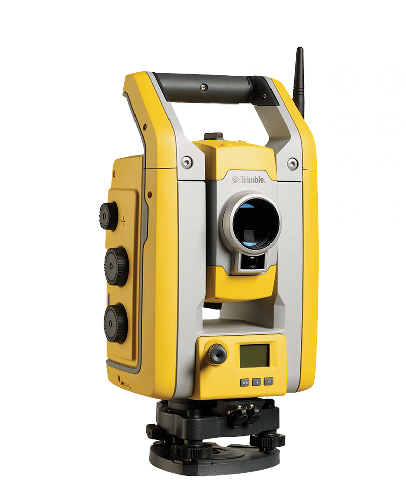
A laser tracker and a total station measure the same three things — two angles and a distance — and the laser tracker is more accurate on all three, most dramatically on distance, where it is tens to hundreds of times more precise. It also takes enough readings per second that noisy ones can be thrown out before they ever reach the robot. That is why Dusty's system is built around a laser tracker rather than the total station most construction teams already own: it is simply the better measuring instrument, and layout accuracy is the whole job.
 |
What the two instruments have in common
Both instruments find a point in 3D space the same way. They measure a horizontal angle, a vertical angle, and a distance to a reflector. The two angles say which direction the reflector is in; the distance says how far away it is along that direction.
Those three measurements are taken independently, and each carries its own error. The instrument's overall position accuracy is the combination of them. The laser tracker is the more accurate instrument on every one of the three — but by wildly different margins, and that is what shapes how the FieldPrinter is built.
Where each instrument's error comes from
Every instrument has one measurement that limits it. On a total station, that measurement is distance, and it is the weakest of the three by a wide margin. On a laser tracker, distance is so precise that the angles become the limiting factor instead — even though those angles are still at least as good as a total station's.
This is the part that gets misread. "Angles are the tracker's weaker measurement" is a statement about the tracker compared with itself. Against a total station, the tracker's angles hold their own and its distance measurement is in a different class entirely.
| Total station | Laser tracker | |
|---|---|---|
| How distance is measured | Electronic distance measurement (EDM) | Absolute distance measurement using a modulated, polarised light beam |
| Limiting measurement | Distance | Angles |
| Error behavior with range | Distance error stays roughly constant — it does not improve by working closer | Angular error shrinks as you work closer to the instrument |
| Published distance accuracy |
Trimble RTS555/RTS655: ±2 mm + 2 ppm Trimble RTS633: ±3 mm + 2 ppm Topcon GT-1200/600 to a prism: (1 mm + 2 ppm × D) |
Leica AT500 absolute distance meter: ±10 µm + 0.3 µm/m Leica AT930 interferometer: ±0.4 µm + 0.3 µm/m |
| Published angular accuracy |
Trimble RTS555/RTS655: 5″ Trimble RTS633: 3″ horizontal, 2″ vertical Topcon GT-1200/600: 1″, 3″ or 5″ depending on model |
Leica AT500 and AT930 transverse error: ±15 µm + 6 µm/m |
Worked at the distances an operator actually prints at, the Leica figures come out like this:
| Distance from the tracker | Tracker distance error | Tracker position error |
|---|---|---|
| 100 ft (30.5 m) | About 0.0008 in — under a thousandth of an inch | About 1/64 in |
| 200 ft (61 m) | About 0.0011 in | About 1/32 in |
Position error uses Leica's location-error formula of 30 µm + 12 µm/m, the maximum permissible error for a two-face measurement under ISO 10360-10. Both the AT500 and the AT930 publish the same formula.
For comparison, a total station in the field is generally worked to about ±1/8 in of position accuracy. That is roughly eight times the tracker's figure at 100 ft — and unlike the tracker's, it does not improve as you work closer to the instrument, because distance is the measurement limiting it and distance error stays where it is.
The angular comparison runs the same direction, though less dramatically. Worked as an angle, the tracker's transverse error is on the order of an arcsecond at printing distances — comparable to the best construction total stations on the raw number, and better than most of them. The difference in how those numbers are defined is what makes it decisive.
Why the accuracy numbers mean different things
Total station accuracy is published as a standard deviation (1 sigma) under ISO 17123 or DIN 18723. A 1-sigma figure describes the middle of a distribution, not its edge: assuming measurements are normally distributed, roughly 32% will fall outside the stated value, and about 4% will be more than twice it.
Laser tracker accuracy is published as maximum permissible error (MPE) under ISO 10360-10. MPE is a ceiling, not an average: a measurement that exceeds it fails the acceptance test. Leica states that typical results come in at about half the MPE value.
So when a total station and a laser tracker both advertise "1 arcsecond," they are not making the same promise. The total station is describing its average. The tracker is describing its worst case — it will not exceed that figure, while roughly a third of the total station's readings will exceed its own.
That is why matching numbers on paper still favor the tracker heavily. The instruments are specified differently because they are sold to different industries: a surveyor is buying an average, and industrial metrology buys a guarantee.
How often each instrument measures
The second difference is timing. A total station is built to measure a target that is standing still: the operator stops, aims, lets the instrument settle, and shoots the point. A laser tracker is built to lock onto a target and follow it while it moves.
A total station supplies position data to a connected system about 20 times per second. A laser tracker measures much faster: the Leica AT500 takes 100 measurements per second, and the AT930 takes 1,000.
The FieldPrinter does not receive every one of those measurements. The radio link between the tracker and the robot delivers 25 position updates per second, on both trackers. So on update count alone, 25 and 20 are close to the same number — which is the part of this comparison that usually gets told wrong.
The advantage is not how many updates arrive. It is what each update is made of.
| Total station | Dusty and its laser tracker | |
|---|---|---|
| Raw measurements taken per second | About 20 | 100 (AT500) or 1,000 (AT930) |
| Position updates sent to the robot | About 20 | 25 |
| Raw measurements behind each update | 1 | 4 (AT500) or 40 (AT930) |
| Can a bad reading be spotted and thrown out? | No | Yes |
When measurements arrive faster than they need to be passed along, the surplus buys two things. First, a reading that disagrees with the ones around it — a momentary beam disturbance, a vibration, a spike caused by rising heat — can be recognized as an anomaly and discarded. Second, the remaining good readings are averaged into a single value, and averaging cancels random noise: combining 40 readings yields a figure roughly six times less noisy than any one of them alone.
A total station produces one reading per update. There is no second opinion to check it against, so a bad reading cannot be detected and cannot be discarded. It goes straight into the robot's idea of where it is, and nothing in the system knows it was bad.
That is the real difference in timing. Both systems steer on roughly the same number of updates per second. Dusty's updates are cleaner ones.
This matters most exactly where layout is hardest. Measurement noise is worst outdoors in high heat and direct sunlight — the same conditions that make a reflector look like it is shimmering across a hot slab. Those are the conditions in which having spare readings to average is worth the most.
What the difference produces in the field
Knowing the printhead's position precisely, and trusting each position you are given, is what makes several FieldPrinter behaviors possible:
- Printing while moving. The robot does not have to stop, settle and mark each feature. Lines start and stop at the right point at full speed.
- Print merging. Every line that fits inside a single 1-inch print lane is laid down in one pass, because the system can switch the printhead on and off at an exact point in time.
- Seamless swath stitching. Adjacent passes register to each other closely enough that large SVG graphics and scannable QR codes can span several swaths without visible gaps.
- A printhead mounted at the corner of the robot. The tracker measures the reflector, not the printhead. Placing the printhead off-center requires knowing the robot's heading precisely, which comes from an accurate, closely-spaced trail of positions. That is what lets the FieldPrinter print right up against walls and obstacles.
Where else laser trackers are used
Laser trackers come out of industrial metrology rather than construction, which is why most jobsite crews have not seen one before Dusty. They are the standard instrument anywhere a large assembly has to be held to a tolerance far tighter than construction normally works to:
- Particle physics. CERN uses Leica laser trackers for surveying and aligning LHC components and detector assemblies, where beamline elements have to sit within fractions of a millimeter. (LHC Survey Laser Tracker Controls Renovation, CERN Document Server)
- Formula 1. Teams measure assembled cars and individual components with laser trackers, and the FIA uses them for race scrutineering — checking car geometry against an approved digital model using reflectors set at defined points. (Hexagon: Leica Absolute Tracker AT901 gives Red Bull Racing wings · F1 Race Scrutineering, Metrology News)
- Aerospace, heavy fabrication and civil testing. Aircraft assembly, dimensional control of large steel structures, and structural load tests on bridges all use the same class of instrument for the same reason: a portable way to measure a very large object very precisely.
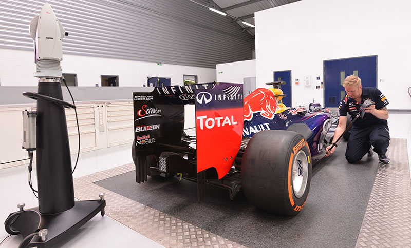
The Dusty FieldPrinter brings that instrument onto the jobsite and points it at a moving robot instead of a static assembly.
What a total station still does better
The laser tracker wins on measurement, but it is not a surveying instrument and does not replace the total station on your site. The two differences are about reach, not precision.
| Total station | Laser tracker | |
|---|---|---|
| Working range to a prism or reflector | Thousands of feet — Topcon GT-1200/600 publishes up to 5,000 m of measuring range to a single prism, and up to 1,000 m of auto-tracking range. |
Leica AT500: 0.8 m to 80 m guaranteed, up to 160 m typical with selected reflectors. Leica AT930: 60 m guaranteed, about 80 m typical, with a 1.5 m minimum lock-on distance. |
| Reflectorless measurement | Yes — measures directly to a surface with no prism. | No. |
| Best use | Surveying, establishing control across a site, long sight lines, as-builts. | Tracking a moving target with metrology-grade precision. |
A total station has a wider beam and a larger aperture, which is what gives it that range. That is the right trade for surveying and the wrong one for guiding a robot across a floor.
This is why the two instruments sit side by side in most Dusty workflows rather than competing. A surveyor sets your control network with a total station; the laser tracker takes that control and puts the robot exactly where the model says a line belongs, to a precision no total station can reach. If you are establishing control for a Dusty job, see What Are Control Points and Why Dusty Needs Them.